Scene to Screen
The next few chapters in this book are focused on the problem of physically based rendering. Given a virtual scene, the goal of physically based rendering is to compute the radiance that would be present in the scene if it were real. However, at that point the work is far from done. The final result?pixel values in the display’s framebuffer?still needs to be determined. In this section we will go over some of the considerations involved in this determination.
High Dynamic Range Display Encoding
The material in this section builds upon Section 5.6, which covers display encoding. We decided to defer coverage of high dynamic range (HDR) displays to this section, since it requires background on topics, such as color gamuts, that had not yet been discussed in that part of the book (RTR4).
Section 5.6 discussed display encoding for standard dynamic range (SDR) monitors, which typically use the sRGB display standard, and SDR televisions, which use the Rec. 709 and Rec. 1886 standards. Both sets of standards have the same RGB gamut and white point (D65), and somewhat similar (but not identical) nonlinear display encoding curves. They also have roughly similar reference white luminance levels (80 $cd/m^2$ for sRGB, 100 $cd/m^2$ for Rec. 709/1886). These luminance specifications have not been closely adhered to by monitor and television manufacturers, who in practice tend to manufacture displays with brighter white levels .
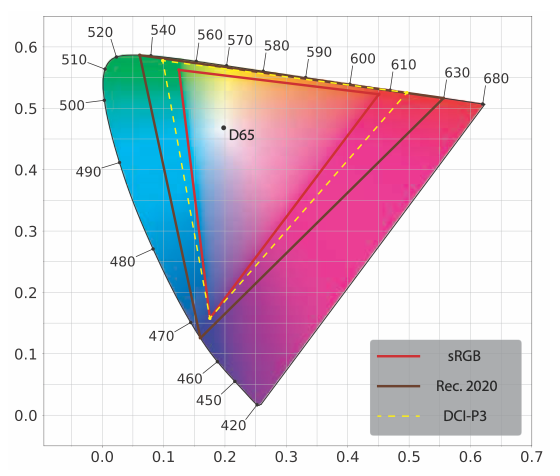
. A CIE 1976 UCS diagram showing the gamuts and white point (D65) of the Rec. 2020 and sRGB/Rec. 709 color spaces. The gamut of the DCI-P3 color space is also shown for comparison.
HDR displays use the Rec. 2020 and Rec. 2100 standards. Rec. 2020 defines a color space with a significantly wider color gamut, as shown in Figure 8.12, and the same white point (D65) as the Rec. 709 and sRGB color spaces. Rec. 2100 defines two nonlinear display encodings: perceptual quantizer (PQ) and hybrid log-gamma (HLG). The HLG encoding is not used much in rendering situations, so we will focus here on PQ, which defines a peak luminance value of $10,000 cd/m^2$.
Although the peak luminance and gamut specifications are important for encoding purposes, they are somewhat aspirational as far as actual displays are concerned. At the time of writing (year 2018), few consumer-level HDR displays have peak luminance levels that exceed even 1500 cd/m2. In practice, display gamuts are much closer to that of DCI-P3 (also shown in Figure 8.12) than Rec. 2020. For this reason, HDR displays perform internal tone and gamut mapping from the standard specifications down to the actual display capabilities. This mapping can be affected by metadata passed by the application to indicate the actual dynamic range and gamut of the content .
From the application side, there are three paths for transferring images to an HDR display, though not all three may be available depending on the display and operating system:
- HDR10?Widely supported on HDR displays as well as PC and console operating systems. The framebuffer format is 32 bits per pixel with 10 unsigned integer bits for each RGB channel and 2 for alpha. It uses PQ nonlinear encoding and Rec. 2020 color space. Each HDR10 display model performs its own tone mapping, one that is not standardized or documented.
- scRGB (linear variant)?Only supported on Windows operating systems. Nominally it uses sRGB primaries and white level, though both can be exceeded since the standard supports RGB values less than 0 and greater than 1. The framebuffer format is 16-bit per channel, and stores linear RGB values. It can work with any HDR10 display since the driver converts to HDR10. It is useful primarily for convenience and backward compatibility with sRGB.
- Dolby Vision?Proprietary format, not yet widely supported in displays or on any consoles (at the time of writing). It uses a custom 12-bit per channel framebuffer format, and uses PQ nonlinear encoding and Rec. 2020 color space. The display internal tone mapping is standardized across models (but not documented).
Lottes points out that there is actually a fourth option. If the exposure and color are adjusted carefully, then an HDR display can be driven through the regular SDR signal path with good results.
With any option other than scRGB, as part of the display-encoding step the application needs to convert the pixel RGB values from the rendering working space to Rec. 2020?which requires a 3 x 3 matrix transform?and to apply the PQ encoding, which is somewhat more expensive than the Rec. 709 or sRGB encoding functions . Patry gives an inexpensive approximation to the PQ curve. Special care is needed when compositing user interface (UI) elements on HDR displays to ensure that the user interface is legible and at a comfortable luminance level .
Tone Mapping
In Sections 5.6 and 8.2.1 we discussed display encoding, the process of converting linear radiance values to nonlinear code values for the display hardware. The function applied by display encoding is the inverse of the display’s electrical optical transfer function (EOTF), which ensures that the input linear values match the linear radiance emitted by the display. Our earlier discussion glossed over an important step that occurs between rendering and display encoding, one that we are now ready to explore.
Tone mapping or tone reproduction is the process of converting scene radiance values to display radiance values. The transform applied during this step is called the end-to-end transfer function, or the scene-to-screen transform. The concept of image state is key to understanding tone mapping . There are two fundamental image states. Scene-referred images are defined in reference to scene radiance values, and display-referred images are defined in reference to display radiance values. Image state is unrelated to encoding. Images in either state may be encoded linearly or nonlinearly. Figure 8.13 shows how image state, tone mapping, and display encoding fit together in the imaging pipeline, which handles color values from initial rendering to final display.
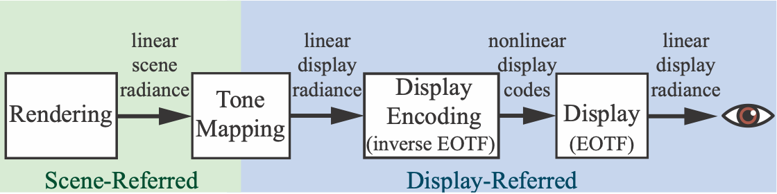
Figure 8.13. The imaging pipeline for synthetic (rendered) images. We render linear scene-referred radiance values, which tone mapping converts to linear display-referred values. Display encoding applies the inverse EOTF to convert the linear display values to nonlinearly encoded values (codes), which are passed to the display. Finally, the display hardware applies the EOTF to convert the nonlinear display values to linear radiance emitted from the screen to the eye.
There are several common misconceptions regarding the goal of tone mapping. It is not to ensure that the scene-to-screen transform is an identity transform, perfectly reproducing scene radiance values at the display. It is also not to “squeeze” every bit of information from the high dynamic range of the scene into the lower dynamic range of the display, though accounting for differences between scene and display dynamic range does play an important part.
To understand the goal of tone mapping, it is best to think of it as an instance of image reproduction . The goal of image reproduction is to create a displayreferred image that reproduces?as closely as possible, given the display properties and viewing conditions?the perceptual impression that the viewer would have if they were observing the original scene.
There is a type of image reproduction that has a slightly different goal. Preferred image reproduction aims at creating a display-referred image that looks better, in some sense, than the original scene. Preferred image reproduction will be discussed later, in Section 8.2.3.
The goal of reproducing a similar perceptual impression as the original scene is a challenging one, considering that the range of luminance in a typical scene exceeds display capabilities by several orders of magnitude. The saturation (purity) of at least some of the colors in the scene are also likely to far outstrip display capabilities. Nevertheless, photography, television, and cinema do manage to produce convincing perceptual likenesses of original scenes, as did Renaissance painters. This achievement is possible by leveraging certain properties of the human visual system.
The visual system compensates for differences in absolute luminance, an ability called adaptation. Due to this ability, a reproduction of an outdoor scene shown on a screen in a dim room can produce a similar perception as the original scene, although the luminance of the reproduction is less than 1% of the original. However, the compensation provided by adaptation is imperfect. At lower luminance levels the perceived contrast is decreased (the Stevens effect), as is the perceived “colorfulness”(the Hunt effect).
Other factors affect actual or perceived contrast of the reproduction. The surround of the display (the luminance level outside the display rectangle, e.g., the brightness of the room lighting) may increase or decrease perceived contrast (the BartlesonBreneman effect). Display flare, which is unwanted light added to the displayed image via display imperfections or screen reflections, reduces the actual contrast of the image, often to a considerable degree. These effects mean that if we want to preserve a similar perceptual effect as the original scene, we must boost the contrast and saturation of the display-referred image values .
However, this increase in contrast exacerbates an existing problem. Since the dynamic range of the scene is typically much larger than that of the display, we have to choose a narrow window of luminance values to reproduce, with values above and below that window being clipped to black or white. Boosting the contrast further narrows this window. To partially counteract the clipping of dark and bright values, a soft roll-off is used to bring some shadow and highlight detail back.
All this results in a sigmoid (s-shaped) tone-reproduction curve, similar to the one provided by photochemical film . This is no accident. The properties of photochemical film emulsion were carefully adjusted by researchers at Kodak and other companies to produce effective and pleasing image reproduction. For these reasons, the adjective “filmic” often comes up in discussions of tone mapping.
The concept of exposure is critical for tone mapping. In photography, exposure refers to controlling the amount of light that falls on the film or sensor. However, in rendering, exposure is a linear scaling operation performed on the scene-referred image before the tone reproduction transform is applied. The tricky aspect of exposure is to determine what scaling factor to apply. The tone reproduction transform and exposure are closely tied together. Tone transforms are typically designed with the expectation that they will be applied to scene-referred images that have been exposed a certain way.
The process of scaling by exposure and then applying a tone reproduction transform is a type of global tone mapping, in which the same mapping is applied to all pixels. In contrast, a local tone mapping process uses different mappings pixel to pixel, based on surrounding pixels and other factors. Real-time applications have almost exclusively used global tone mapping (with a few exceptions ), so we will focus on this type, discussing first tone-reproduction transforms and then exposure.
It is important to remember that scene-referred images and display-referred images are fundamentally different. Physical operations are only valid when performed on scene-referred data. Due to display limitations and the various perceptual effects we have discussed, a nonlinear transform is always needed between the two image states.
Tone Reproduction Transform
Tone reproduction transforms are often expressed as one-dimensional curves mapping scene-referred input values to display-referred output values. These curves can be applied either independently to R, G, and B values or to luminance. In the former case, the result will automatically be in the display gamut, since each of the displayreferred RGB channel values will be between 0 and 1. However, performing nonlinear operations (especially clipping) on RGB channels may cause shifts in saturation and hue, besides the desired shift in luminance. Giorgianni and Madden point out that the shift in saturation can be perceptually beneficial. The contrast boost that most reproduction transforms use to counteract the Stevens effect (as well as surround and viewing flare effects) will cause a corresponding boost in saturation, which will counteract the Hunt effect as well. However, hue shifts are generally regarded as undesirable, and modern tone transforms attempt to reduce them by applying additional RGB adjustments after the tone curve.
By applying the tone curve to luminance, hue and saturation shifts can be avoided (or at least reduced). However, the resulting display-referred color may be out of the display’s RGB gamut, in which case it will need to be mapped back in.
One potential issue with tone mapping is that applying a nonlinear function to scene-referred pixel colors can cause problems with some antialiasing techniques. The issue (and methods to address it) are discussed in Section 5.4.2.
The Reinhard tone reproduction operator is one of the earlier tone transforms used in real-time rendering. It leaves darker values mostly unchanged, while brighter values asymptotically go to white. A somewhat-similar tone-mapping operator was proposed by Drago et al. with the ability to adjust for output display luminance, which may make it a better fit for HDR displays. Duiker created an approximation to a Kodak film response curve for use in video games. This curve was later modified by Hable to add more user control, and was used in the game Uncharted 2. Hable’s presentation on this curve was influential, leading to the “Hable filmic curve” being used in several games. Hable later proposed a new curve with a number of advantages over his earlier work.
Day presents a sigmoid tone curve that was used on titles from Insomniac Games, as well as the game Call of Duty: Advanced Warfare. Gotanda created tone transforms that simulate the response of film as well as digital camera sensors. These were used on the game Star Ocean 4 and others. Lottes points out that the effect of display flare on the effective dynamic range of the display is significant and highly dependent on room lighting conditions. For this reason, it is important to provide user adjustments to the tone mapping. He proposes a tone reproduction transform with support for such adjustments that can be used with SDR as well as HDR displays.
The Academy Color Encoding System (ACES) was created by the Science and Technology Council of the Academy of Motion Picture Arts and Sciences as a proposed standard for managing color for the motion picture and television industries. The ACES system splits the scene-to-screen transform into two parts. The first is the reference rendering transform (RRT), which transforms scene-referred values into display-referred values in a standard, device-neutral output space called the output color encoding specification (OCES). The second part is the output device transform (ODT), which converts color values from OCES to the final display encoding. There are many different ODTs, each one designed for a specific display device and viewing condition. The concatenation of the RRT and the appropriate ODT creates the overall transform. This modular structure is convenient for addressing a variety of display types and viewing conditions. Hart recommends the ACES tone mapping transforms for applications that need to support both SDR and HDR displays.
Although ACES was designed for use in film and television, its transforms are seeing growing use in real-time applications. ACES tone mapping is enabled by default in the Unreal Engine , and it is supported by the Unity engine as well . Narkowicz gives inexpensive curves fitted to the ACES RRT with SDR and HDR ODTs , as does Patry . Hart presents a parameterized version of the ACES ODTs to support a range of devices.
Tone mapping with HDR displays requires some care, since the displays will also apply some tone mapping of their own. Fry presents a set of tone mapping transforms used in the Frostbite game engine. They apply a relatively aggressive tone reproduction curve for SDR displays, a less-aggressive one for displays using the HDR10 signal path (with some variation based on the peak luminance of the display), and no tone mapping with displays using the Dolby Vision path (in other words, they rely upon the built-in Dolby Vision tone mapping applied by the display). The Frostbite tone reproduction transforms are designed to be neutral, without significant contrast or hue changes. The intent is for any desired contrast or hue modifications to be applied via color grading (Section 8.2.3). To this end, the tone reproduction transform is applied in the $IC_TC_P$ color space , which was designed for perceptual uniformity and orthogonality between the chrominance and luminance axes. The Frostbite transform tone-maps the luminance and increasingly desaturates the chromaticity as the luminance rolls off to display white. This provides a clean transform without hue shifts.
Ironically, following issues with assets (such as fire effects) that were authored to leverage the hue shifts in their previous transform, the Frostbite team ended up modifying the transform, enabling users to re-introduce some degree of hue shifting to the display-referred colors. Figure 8.15 shows the Frostbite transform compared with several others mentioned in this section.
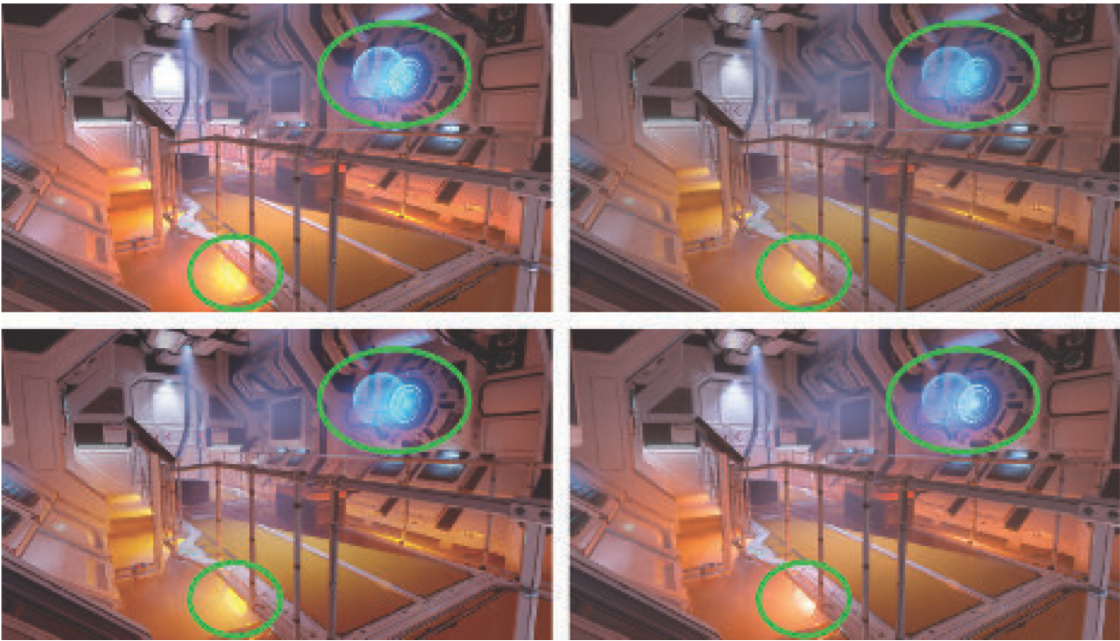
Figure 8.15. A scene with four different tone transforms applied. Differences are primarily seen in the circled areas, where scene pixel values are especially high. Upper left: clipping (plus sRGB OETF); upper right: Reinhard ; lower left: Duiker ; lower right: Frostbite (hue-preserving version) . The Reinhard, Duiker, and Frostbite transforms all preserve highlight information lost by clipping. However, the Reinhard curve tends to desaturate the darker parts of the image , while the Duiker transform increases saturation in darker regions, which is sometimes regarded as a desirable trait . By design, the Frostbite transform preserves both saturation and hue, avoiding the strong hue shift that can be seen in the lower left circle on the other three images.
Exposure
A commonly used family of techniques for computing exposure relies on analyzing the scene-referred luminance values. To avoid introducing stalls, this analysis is typically done by sampling the previous frame.
Following a recommendation by Reinhard et al. , one metric that was used in earlier implementations is the log-average scene luminance. Typically, the exposure was determined by computing the log-average value for the frame . This log-average is computed by performing a series of down-sampling post-process passes, until a final, single value for the frame is computed.
Using an average value tends to be too sensitive to outliers, e.g., a small number of bright pixels could affect the exposure for the entire frame. Subsequent implementations ameliorated this problem by instead using a histogram of luminance values. Instead of the average, a histogram allows computing the median, which is more robust. Additional data points in the histogram can be used for improved results. For example, in The Orange Box by Valve, heuristics based on the 95th percentile and the median were used to determine exposure . Mittring describes the use of compute shaders to generate the luminance histogram .
The problem with the techniques discussed so far is that pixel luminance is the wrong metric for driving exposure. If we look at photography practices, such as Ansel Adams’ Zone System and how incident light meters are used to set exposure, it becomes clear that it is preferable to use the lighting alone (without the effect of surface albedo) to determine exposure . Doing so works because, to a first approximation, photographic exposure is used to counteract lighting. This results in a print that shows primarily the surface colors of objects, which corresponds to the color constancy property of the human visual system. Handling exposure in this way also ensures that correct values are passed to the tone transform. For example, most tone transforms used in the film or television industry are designed to map the exposed scene-referred value 0.18 to the display-referred value 0.1, with the expectation that 0.18 represents an 18% gray card in the dominant scene lighting .
Although this approach is not yet common in real-time applications, it is starting to see use. For example, the game Metal Gear Solid V: Ground Zeroes has an exposure system based on lighting intensity . In many games, static exposure levels are manually set for different parts of the environment based on known scene lighting values. Doing so avoids unexpected dynamic shifts in exposure.
Color Grading
In Section 8.2.2 we mentioned the concept of preferred image reproduction, the idea of producing an image that looks better in some sense than the original scene. Typically this involves creative manipulation of image colors, a process known as color grading.
Digital color grading has been used in the movie industry for some time. Color grading is typically performed by interactively manipulating the colors in an example scene image, until the desired creative “look” is achieved. The same sequence of operations is then re-applied across all the images in a shot or sequence. Color grading spread from movies to games, where it is now widely used .
Selan shows how to “bake” arbitrary color transformations from a color grading or image editing application into a three-dimensional color lookup table (LUT). Such tables are applied by using the input R, G, and B values as x-, y-, and zcoordinates for looking up a new color in the table, and thus can be used for any mapping from input to output color, up to the limitation of the LUT’s resolution. Selan’s baking process starts by taking an identity LUT (one that maps every input color to the same color) and “slicing” it to create a two-dimensional image. This sliced LUT image is then loaded into a color grading application, and the operations that define a desired creative look are applied to it. Care is needed to apply only color operations to the LUT, avoiding spatial operations such as blurs. The edited LUT is then saved out, “packed” into a three-dimensional GPU texture, and used in a rendering application to apply the same color transformations on the fly to rendered pixels. Iwanicki presents a clever way to reduce sampling errors when storing a color transform in a LUT, using least-squares minimization.
In a later publication, Selan distinguishes between two ways to perform color grading. In one approach, color grading is performed on display-referred image data. In the other, the color grading operations are performed on scene-referred data that is previewed through a display transform. Although the display-referred color grading approach is easier to set up, grading scene-referred data can produce higher-fidelity results.
When real-time applications first adopted color grading, the display-referred approach was predominant . However, the scene-referred approach has since been gaining traction due to its higher visual quality. Applying color grading to scene-referred data also provides the opportunity to save some computation by baking the tone mapping curve into the grading LUT , as done in the game Uncharted 4 .
Before LUT lookup, scene-referred data must be remapped to the range. In the Frostbite engine the perceptual quantizer OETF is used for this purpose, though simpler curves could be used. Duiker uses a log curve, and Hable recommends using a square root operator applied once or twice. Hable presents a good overview of common color grading operations and implementation considerations.