In this chapter we cover the various aspects of physically based shading. We start with a description of the physics of light-matter interaction in Section 9.1, and in Sections 9.2 to 9.4 we show how these physics connect to the shading process. Sections 9.5 to 9.7 are dedicated to the building blocks used to construct physically based shading models, and the models themselves?covering a broad variety of material types?are discussed in Sections 9.8 to 9.12. Finally, in Section 9.13 we describe how materials are blended together, and we cover filtering methods for avoiding aliasing and preserving surface appearance.
Physically Based Shading
The interactions of light and matter form the foundation of physically based shading. To understand these interactions, it helps to have a basic understanding of the nature of light.
In physical optics, light is modeled as an electromagnetic transverse wave, a wave that oscillates the electric and magnetic fields perpendicularly to the direction of its propagation. The oscillations of the two fields are coupled. The magnetic and electric field vectors are perpendicular to each other and the ratio of their lengths is fixed. This ratio is equal to the phase velocity, which we will discuss later.
As we have seen in Section 8.1, the perceived color of light is strongly related to its wavelength. For this reason, light with a single wavelength is called monochromatic light, which means “single-colored.” However, most light waves encountered in practice are polychromatic, containing many different wavelengths.
In contrast, in this book we focus on unpolarized light, which is much more prevalent. In unpolarized light the field oscillations are spread equally over all directions perpendicular to the propagation axis. Despite their simplicity, it is useful to understand the behavior of monochromatic, linearly polarized waves, since any light wave can be factored into a combination of such waves.
If we track a point on the wave with a given phase (for example, an amplitude peak) over time, we will see it move through space at a constant speed, which is the wave’s phase velocity. For a light wave traveling through a vacuum, the phase velocity is c, commonly referred to as the speed of light, about 300,000 kilometers per second.
In Section 8.1.1 we discussed the fact that for visible light, the size of a single wavelength is in the range of approximately 400?700 nanometers. In optics it is often useful to talk about the size of features relative to light wavelength. In this case we would say that the width of a spider silk thread is about 2$\lambda$?3$\lambda$ (2?3 light wavelengths), and the width of a hair is about 100$\lambda$?200$\lambda$.
Light waves carry energy. The density of energy flow is equal to the product of the magnitudes of the electric and magnetic fields, which is?since the magnitudes are proportional to each other?proportional to the squared magnitude of the electric field. We focus on the electric field since it affects matter much more strongly than the magnetic field. In rendering, we are concerned with the average energy flow over time, which is proportional to the squared wave amplitude. This average energy flow density is the irradiance, denoted with the letter E. Irradiance and its relation to other light quantities were discussed in Section 8.1.1.
Depending on the relative phase relationships, coherent addition of n identical waves can result in a wave with irradiance anywhere between 0 and n2times that of an individual wave
However, most often when waves are added up they are mutually incoherent, which means that their phases are relatively random. In this scenario, the amplitude of the combined wave is $\sqrt{n} a$, and the irradiance of the individual waves adds up linearly to n times the irradiance of one wave, as one would expect.
Light waves are emitted when the electric charges in an object oscillate. Part of the energy that caused the oscillations?heat, electrical energy, chemical energy?is converted to light energy, which is radiated away from the object. In rendering, such objects are treated as light sources. We first discussed light sources in Section 5.2, and they will be described from a more physically based standpoint in Chapter 10.
After light waves have been emitted, they travel through space until they encounter some bit of matter with which to interact. The core phenomenon underlying the majority of light-matter interactions is simple, and quite similar to the emission case discussed above. The oscillating electrical field pushes and pulls at the electrical charges in the matter, causing them to oscillate in turn. The oscillating charges emit new light waves, which redirect some of the energy of the incoming light wave in new directions. This reaction, called scattering, is the basis of a wide variety of optical phenomena.
A scattered light wave has the same frequency as the original wave. When, as is usually the case, the original wave contains multiple frequencies of light, each one interacts with matter separately. Incoming light energy at one frequency does not contribute to emitted light energy at a different frequency, except for specific-and relatively rare-cases such as fluorescence and phosphorescence, which we will not describe in this book.
An isolated molecule scatters light in all directions, with some directional variation in intensity. More light is scattered in directions close to the original axis of propagation, both forward and backward. The molecule’s effectiveness as a scatterer-the chance that a light wave in its vicinity will be scattered at all-varies strongly by wavelength. Short-wavelength light is scattered much more effectively than longerwavelength light.
In rendering we are concerned with collections of many molecules. Light interactions with such aggregates will not necessarily resemble interactions with isolated molecules. Waves scattered from nearby molecules are often mutually coherent, and thus exhibit interference, since they originate from the same incoming wave. The rest of this section is devoted to several important special cases of light scattering from multiple molecules.
Particles
In an ideal gas, molecules do not affect each other and thus their relative positions are completely random and uncorrelated. Although this is an abstraction, it is a reasonably good model for air at normal atmospheric pressure. In this case, the phase differences between waves scattered from different molecules are random and constantly changing. As a result, the scattered waves are incoherent and their energy adds linearly. In other words, the aggregate light energy scattered from n molecules is n times the light scattered from a single molecule.
In contrast, if the molecules are tightly packed into clusters much smaller than a light wavelength, the scattered light waves in each cluster are in phase and interfere constructively. This causes the scattered wave energy to add up quadratically. Thus the intensity of light scattered from a small cluster of n molecules is n2times the light scattered from an individual molecule, which is n times more light than the same number of molecules would scatter in an ideal gas. This relationship means that for a fixed density of molecules per cubic meter, clumping the molecules into clusters will significantly increase the intensity of scattered light. Making the clusters larger, while still keeping the overall molecular density constant, will further increase scattered light intensity, until the cluster diameter becomes close to a light wavelength. Beyond that point, additional increases in cluster size will not further increase the scattered light intensity .
This process explains why clouds and fog scatter light so strongly. They are both created by condensation, which is the process of water molecules in the air clumping together into increasingly large clusters. This significantly increases light scattering, even though the overall density of water molecules is unchanged. Cloud rendering is discussed in Section 14.4.2.
When discussing light scattering, the term particles is used to refer to both isolated molecules and multi-molecule clusters. Since scattering from multi-molecule particles with diameters smaller than a wavelength is an amplified (via constructive interference) version of scattering from isolated molecules, it exhibits the same directional variation and wavelength dependence. This type of scattering is called Rayleigh scattering in the case of atmospheric particles and Tyndall scattering in the case of particles embedded in solids.
As particle size increases beyond a wavelength, the fact that the scattered waves are no longer in phase over the entire particle changes the characteristics of the scattering. The scattering increasingly favors the forward direction, and the wavelength dependency decreases until light of all visible wavelengths is scattered equally. This type of scattering is called Mie scattering. Rayleigh and Mie scattering are covered in more detail in Section 14.1.
Media
Another important case is light propagating through a homogeneous medium, which is a volume filled with uniformly spaced identical molecules. The molecular spacing does not have to be perfectly regular, as in a crystal. Liquids and non-crystalline solids can be optically homogeneous if their composition is pure (all molecules are the same) and they have no gaps or bubbles.
In a homogeneous medium, the scattered waves are lined up so that they interfere destructively in all directions except for the original direction of propagation. After the original wave is combined with all the waves scattered from individual molecules, the final result is the same as the original wave, except for its phase velocity and (in some cases) amplitude. The final wave does not exhibit any scattering-it has effectively been suppressed by destructive interference.
The ratio of the phase velocities of the original and new waves defines an optical property of the medium called the index of refraction (IOR) or refractive index, denoted by the letter $n$. Some media are absorptive. They convert part of the light energy to heat, causing the wave amplitude to decrease exponentially with distance. The rate of decrease is defined by the attenuation index, denoted by the Greek letter $\kappa$ (kappa). Both $n$ and $\kappa$ typically vary by wavelength. Together, these two numbers fully define how the medium affects light of a given wavelength, and they are often combined into a single complex number $n + i\kappa$, called the complex index of refraction. The index of refraction abstracts away the molecule-level details of light interaction and enables treating the medium as a continuous volume, which is much simpler.
While the phase velocity of light does not directly affect appearance, changes in velocity do, as we will explain later. On the other hand, light absorption has a direct impact on visuals, since it reduces the intensity of light and can (if varying by wavelength) also change its color.
Nonhomogeneous media can often be modeled as homogeneous media with embedded scattering particles. The destructive interference that suppresses scattering in homogeneous media is caused by the uniform alignment of molecules, and thus of the scattered waves they produce. Any localized change in the distribution of molecules will break this pattern of destructive interference, allowing scattered light waves to propagate. Such a localized change can be a cluster of a different molecule type, an air gap, a bubble, or density variation. In any case, it will scatter light like the particles discussed earlier, with scattering properties similarly dependent on the cluster’s size. Even gases can be modeled in this way. For these, the “scattering particles”are transient density fluctuations caused by the constant motion of the molecules. This model enables establishing a meaningful value of n for gases, which is useful for understanding their optical properties.
Scattering and absorption are both scale-dependent. A medium that does not produce any apparent scattering in a small scene may have quite noticeable scattering at larger scales. For example, light scattering in air and absorption in water are not visible when observing a glass of water in a room. However, in extended environments both effects can be significant.
In the general case, a medium’s appearance is caused by some combination of scattering and absorption. The degree of scattering determines cloudiness, with high scattering creating an opaque appearance. With somewhat rare exceptions, such as the opalescent glass, particles in solid and liquid media tend to be larger than a light wavelength, and tend to scatter light of all visible wavelengths equally. Thus any color tint is usually caused by the wavelength dependence of the absorption. The lightness of the medium is a result of both phenomena. A white color in particular is the result of a combination of high scattering and low absorption. This is discussed in more detail in Section 14.1.
Surfaces
From an optical perspective, an object surface is a two-dimensional interface separating volumes with different index of refraction values. In typical rendering situations, the outer volume contains air, with a refractive index of about 1.003, often assumed to be 1 for simplicity. The refractive index of the inner volume depends on the substance from which the object is made.
When a light wave strikes a surface, two aspects of that surface have important effects on the result: the substances on either side, and the surface geometry. We will start by focusing on the substance aspect, assuming the simplest-possible surface geometry, a perfectly flat plane. We denote the index of refraction on the “outside”(the side where the incoming, or incident, wave originates) as $n_1$ and the index of refraction on the “inside” (where the wave will be transmitted after passing through the surface) as $n_2$.
We have seen in the previous section that light waves scatter when they encounter a discontinuity in material composition or density, i.e., in the index of refraction. A planar surface separating different indices of refraction is a special type of discontinuity that scatters light in a specific way. The boundary conditions require that the electrical field component parallel to the surface is continuous. In other words, the projection of the electric field vector to the surface plane must match on either side of the surface. This has several implications:
- At the surface, any scattered waves must be either in phase, or 180?out of phase, with the incident wave. Thus at the surface, the peaks of the scattered waves must line up either with the peaks or the troughs of the incident wave. This restricts the scattered waves to go in only two possible directions, one continuing forward into the surface and one retreating away from it. The first of these is the transmitted wave, and the second is the reflected wave.
- The scattered waves must have the same frequency as the incident wave. We assume a monochromatic wave here, but the principles we discuss can be applied to any general wave by first decomposing it into monochromatic components.
- As a light wave moves from one medium to another, the phase velocity-the speed the wave travels through the medium-changes proportionally to the relative index of refraction ($n_1/n_2$). Since the frequency is fixed, the wavelength also changes proportionally to ($n_1/n_2$).
The reflected and incident wave directions have the same angle $\theta_i$ with the surface normal. The transmitted wave direction is bent (refracted) at an angle $\theta_t$, which has the following relation to $\theta_i$: \(\sin(\theta_t) = \frac{n_1}{n_2} \sin(\theta_i).\) This equation for refraction is known as Snell’s law. It is used in global refraction effects, which will be discussed further in Section 14.5.2.
Although refraction is often associated with clear materials such as glass and crystal, it happens at the surface of opaque objects as well. When refraction occurs with opaque objects, the light undergoes scattering and absorption in the object’s interior. Light interacts with the object’s medium. In the case of metals, the interior contains many free electrons (electrons not bound to molecules) that “soak up” the refracted light energy and redirect it into the reflected wave. This is why metals have high absorption as well as high reflectivity.
The surface refraction phenomena we have discussed-reflection and refraction-require an abrupt change in index of refraction, occurring over a distance of less than a single wavelength. A more gradual change in index of refraction does not split the light, but instead causes its path to curve, in a continuous analog of the discontinuous bend that occurs in refraction. This effect commonly can be seen when air density varies due to temperature, such as mirages and heat distortion.
Even an object with a well-defined boundary will have no visible surface if it is immersed in a substance with the same index of refraction. In the absence of an index of refraction change, reflection and refraction cannot occur.
Until now we have focused on the effect of the substances on either side of a surface. We will now discuss the other important factor affecting surface appearance: geometry. Strictly speaking, a perfectly flat planar surface is impossible. Every surface has irregularities of some kind, even if only the individual atoms comprising the surface. However, surface irregularities much smaller than a wavelength have no effect on light, and surface irregularities much larger than a wavelength effectively tilt the surface without affecting its local flatness. Only irregularities with a size in the range of 1?100 wavelengths cause the surface to behave differently than a flat plane, via a phenomenon called diffraction that will be discussed further in Section 9.11.
In rendering, we typically use geometrical optics, which ignores wave effects such as interference and diffraction. This is equivalent to assuming that all surface irregularities are either smaller than a light wavelength or much larger. In geometrical optics light is modeled as rays instead of waves. At the point a light ray intersects with a surface, the surface is treated locally as a flat plane. We will keep to the realm of geometrical optics from this point until Section 9.11, which is dedicated to the topic of shading models based on wave optics.
As we mentioned earlier, surface irregularities much larger than a wavelength change the local orientation of the surface. When these irregularities are too small to be individually rendered-in other words, smaller than a pixel-we refer to them as microgeometry. The directions of reflection and refraction depend on the surface normal. The effect of the microgeometry is to change that normal at different points on the surface, thus changing the reflected and refracted light directions.
Even though each specific point on the surface reflects light in only a single direction, each pixel covers many surface points that reflect light in various directions. The appearance is driven by the aggregate result of all the different reflection directions. Figure 9.12 shows an example of two surfaces that have similar shapes on the macroscopic scale but significantly different microgeometry.
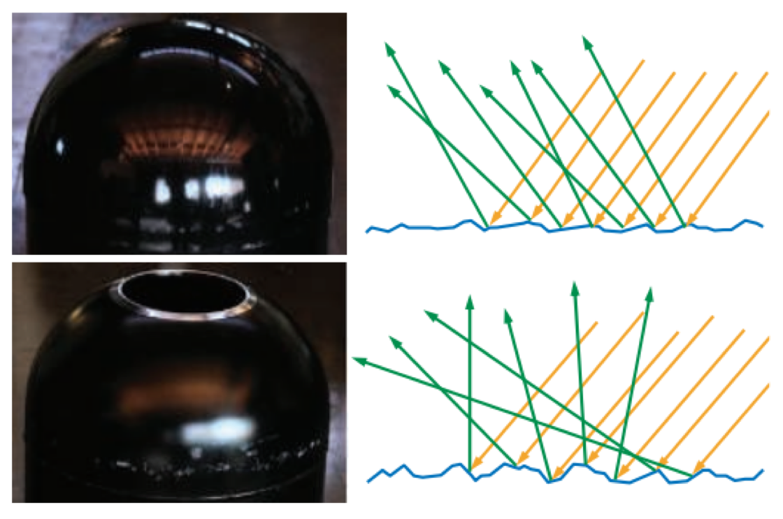
Figure 9.12: On the left we see photographs of two surfaces, with diagrams of their microscopic structures on the right. The top surface has slightly rough microgeometry. Incoming light rays hit surface points that are angled somewhat differently and reflect in a narrow cone of directions. The visible effect is a slight blurring of the reflection. The bottom surface has rougher microgeometry. Surface points hit by incoming light rays are angled in significantly different directions and the reflected light spreads out in a wide cone, causing blurrier reflections.
For rendering, rather than modeling the microgeometry explicitly, we treat it statistically and view the surface as having a random distribution of microstructure normals. As a result, we model the surface as reflecting (and refracting) light in a continuous spread of directions. The width of this spread, and thus the blurriness of reflected and refracted detail, depends on the statistical variance of the microgeometry normal vectors-in other words, the surface microscale roughness.
Subsurface Scattering
Refracted light continues to interact with the interior volume of the object. As mentioned earlier, metals reflect most incident light and quickly absorb the rest. In contrast, non-metals exhibit a wide variety of scattering and absorption behaviors. Materials with low scattering and absorption are transparent, transmitting any refracted light through the entire object. Simple methods for rendering such materials without refraction were discussed in Section 5.5, and refraction will be covered in detail in Section 14.5.2. In this chapter we will focus on opaque objects, in which the transmitted light undergoes multiple scattering and absorption events until finally some of it is re-emitted back from the surface.
This subsurface-scattered light exits the surface at varying distances from the entry point. The distribution of entry-exit distances depends on the density and properties of the scattering particles in the material. The relationship between these distances and the shading scale (the size of a pixel, or the distance between shading samples) is important. If the entry-exit distances are small compared to the shading scale, they can be assumed to be effectively zero for shading purposes. This allows subsurface scattering to be combined with surface reflection into a local shading model, with outgoing light at a point depending only on incoming light at the same point. However, since subsurface-scattered light has a significantly different appearance than surfacereflected light, it is convenient to divide them into separate shading terms. The specular term models surface reflection, and the diffuse term models local subsurface scattering.
If the entry-exit distances are large compared to the shading scale, then specialized rendering techniques are needed to capture the visual effect of light entering the surface at one point and leaving it from another. These global subsurface scattering techniques are covered in detail in Section 14.6. The difference between local and global subsurface scattering is illustrated in Figure 9.15.
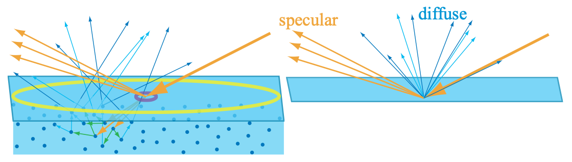
Figure 9.15: On the left, we are rendering a material with subsurface scattering. Two different sampling sizes are shown, in yellow and purple. The large yellow circle represents a single shading sample covering an area larger than the subsurface scattering distances. Thus, those distances can be ignored, enabling subsurface scattering to be treated as the diffuse term in a local shading model, as shown in the separate figure on the right. If we move closer to this surface, the shading sample area becomes smaller, as shown by the small purple circle. The subsurface scattering distances are now large compared to the area covered by a shading sample. Global techniques are needed to produce a realistic image from these samples.
It is important to note that local and global subsurface scattering techniques model exactly the same physical phenomena. The best choice for each situation depends not only on the material properties but also on the scale of observation. For example, when rendering a scene of a child playing with a plastic toy, it is likely that global techniques would be needed for an accurate rendering of the child’s skin, and that a local diffuse shading model would suffice for the toy. This is because the scattering distances in skin are quite a bit larger than in plastic. However, if the camera is far enough away, the skin scattering distances would be smaller than a pixel and local shading models would be accurate for both the child and the toy. Conversely, in an extreme close-up shot, the plastic would exhibit noticeable non-local subsurface scattering and global techniques would be needed to render the toy accurately.