Microgeometry
As we discussed earlier in Section 9.1.3, surface irregularities much smaller than a pixel cannot feasibly be modeled explicitly, so the BRDF instead models their aggregate effect statistically. For now we keep to the domain of geometrical optics, which assumes that these irregularities either are smaller than a light wavelength (and so have no effect on the light’s behavior) or are much larger. The effects of irregularities that are in the “wave optics domain” (around 1?100 wavelengths in size) will be discussed in Section 9.11.
Each visible surface point contains many microsurface normals that bounce the reflected light in different directions. Since the orientations of individual microfacets are somewhat random, it makes sense to model them as a statistical distribution. For most surfaces, the distribution of microgeometry surface normals is continuous, with a strong peak at the macroscopic surface normal. The “tightness” of this distribution is determined by the surface roughness. The rougher the surface, the more “spread out” the microgeometry normals will be.
The visible effect of increasing microscale roughness is greater blurring of reflected environmental detail. In the case of small, bright light sources, this blurring results in broader and dimmer specular highlights. Those from rougher surfaces are dimmer because the light energy is spread into a wider cone of directions.
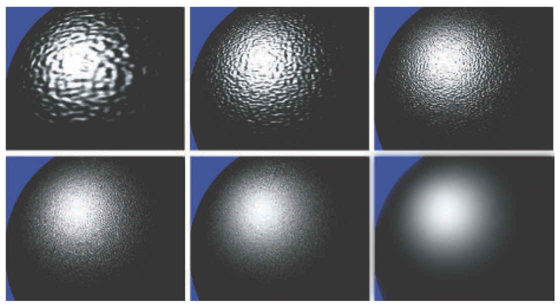
Figure 9.25. Gradual transition from visible detail to microscale. The sequence of images goes top row left to right, then bottom row left to right. The surface shape and lighting are constant. Only the scale of the surface detail changes.
Figure 9.25 shows how visible reflectance results from the aggregate reflections of the individual microscale surface details. The series of images shows a curved surface lit by a single light, with bumps that steadily decrease in scale until in the last image the bumps are much smaller than a single pixel. Statistical patterns in the many small highlights eventually become details in the shape of the resulting aggregate highlight. For example, the relative sparsity of individual bump highlights in the periphery becomes the relative darkness of the aggregate highlight away from its center.
For most surfaces, the distribution of the microscale surface normals is isotropic, meaning it is rotationally symmetrical, lacking any inherent directionality. Other surfaces have microscale structure that is anisotropic. Such surfaces have anisotropic surface normal distributions, leading to directional blurring of reflections and highlights.
Some surfaces have highly structured microgeometry, resulting in a variety of microscale normal distributions and surface appearances. Fabrics are a commonly encountered example?the unique appearance of velvet and satin is due to the structure of their microgeometry . Fabric models will be discussed in Section 9.10.
Although multiple surface normals are the primary effect of microgeometry on reflectance, other effects can also be important. Shadowing refers to occlusion of the light source by microscale surface detail, as shown on the left side of Figure 9.27. Masking, where some facets hide others from the camera, is shown in the center of the figure.
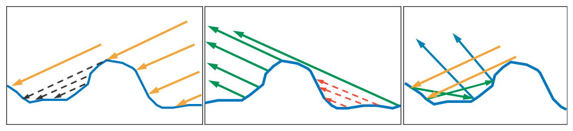
Figure 9.27. Geometrical effects of microscale structure. On the left, the black dashed arrows indicate an area that is shadowed (occluded from the light) by other microgeometry. In the center, the red dashed arrows indicate an area that is masked (occluded from view) by other microgeometry. On the right, interreflection of light between the microscale structures is shown.
If there is a correlation between the microgeometry height and the surface normal, then shadowing and masking can effectively change the normal distribution. For example, imagine a surface where the raised parts have been smoothed by weathering or other processes, and the lower parts remain rough. At glancing angles, the lower parts of the surface will tend to be shadowed or masked, resulting in an effectively smoother surface. See Figure 9.28.
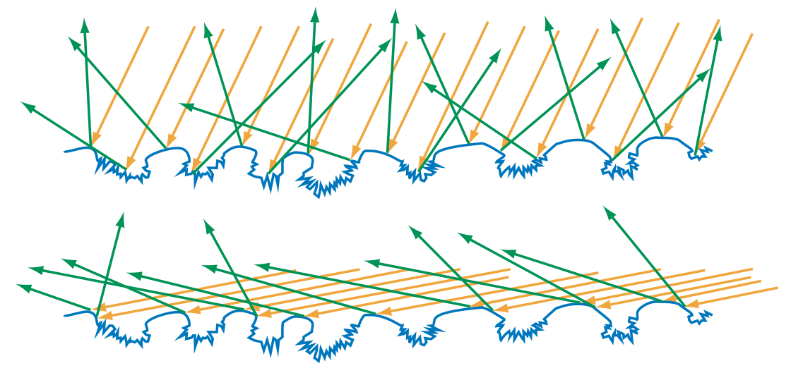
Figure 9.28. The microgeometry shown has a strong correlation between height and surface normal, where the raised areas are smooth and lower areas are rough. In the top image, the surface is illuminated from an angle close to the macroscopic surface normal. At this angle, the rough pits are accessible to many of the incoming light rays, and so many rays are scattered in different directions. In the bottom image, the surface is illuminated from a glancing angle. Shadowing blocks most of the pits, so few light rays hit them, and most rays are reflected from the smooth parts of the surface. In this case, the apparent roughness depends strongly on the angle of illumination.
For all surface types, the visible size of the surface irregularities decreases as the incoming angle $\theta_i$ to the normal increases. At extremely glancing angles, this effect can decrease the viewed size of the irregularities to be shorter than the light’s wavelength, making them “disappear” as far as the light response is concerned. These two effects combine with the Fresnel effect to make surfaces appear highly reflective and mirrorlike as the viewing and lighting angles approach $90^\circ$.
Confirm this for yourself. Roll a sheet of non-shiny paper into a long tube. Instead of looking through the hole, move your eye slightly higher, so you are looking down its length. Point your tube toward a brightly lit window or computer screen. With your view angle nearly parallel to the paper you will see a sharp reflection of the window or screen in the paper. The angle has to be extremely close to 90?to see the effect.
Light that was occluded by microscale surface detail does not disappear. It is reflected, possibly onto other microgeometry. Light may undergo multiple bounces in this way before it reaches the eye. Such interreflections are shown on the right side of Figure 9.27. Since the light is being attenuated by the Fresnel reflectance at each bounce, interreflections tend to be subtle in dielectrics. In metals, multiple-bounce reflection is the source of any visible diffuse reflection, since metals lack subsurface scattering. Multiple-bounce reflections from colored metals are more deeply colored than the primary reflection, since they are the result of light interacting with the surface multiple times.
So far we have discussed the effects of microgeometry on specular reflectance, i.e., the surface reflectance. In certain cases, microscale surface detail can affect subsurface reflectance as well. If the microgeometry irregularities are larger than the subsurface scattering distances, then shadowing and masking can cause a retroreflection effect, where light is preferentially reflected back toward the incoming direction. This effect occurs because shadowing and masking will occlude lit areas when the viewing and lighting directions differ greatly. See Figure 9.29. Retroreflection tends to give rough surfaces a flat appearance.
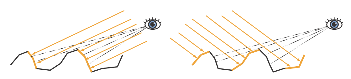
Figure 9.29. Retroreflection due to microscale roughness. Both figures show a rough surface with low Fresnel reflectance and high scattering albedo, so subsurface reflectance is visually important. On the left, the viewing and lighting directions are similar. The parts of the microgeometry that are brightly lit are also the ones that are most visible, leading to a bright appearance. On the right, the viewing and lighting directions differ greatly. In this case, the brightly lit areas are occluded from view and the visible areas are shadowed, leading to a darker appearance.