Implement Shading Models
In this section we will go over some key considerations for designing and writing implementations of shading and lighting equations.
Frequency of Evaluation
- determine whether the result of a given computation is always constant over an entire draw call. In this case, the computation can be performed by the application, typically on the CPU, though a GPU compute shader could be used for especially costly computations.
- once ever: there is a broad range of possible frequencies of evaluation
- a constant subexpression in the shading equation, but this could apply to any computation based on rarely changing factors such as the hardware configuration and installation options
Such shading computations might be resolved when the shader is compiled, in which case there is no need to even set a uniform shader input. Alternatively, the compu- tation might be performed in an offline precomputation pass, at installation time, or when the application is loaded.
- result of a shading computation changes over an application run, but so slowly that updating it every frame is not necessary
lighting factors that depend on the time of day in a virtual game world. If the computation is costly, it may be worthwhile to amortize it over multiple frames.
- computations that are performed once per frame, such as concatenating the view and perspective matrices; or once per model, such as updating model lighting parameters that depend on location; or once per draw call, e.g., updating parameters for each material within a model.
Grouping uniform shader inputs by frequency of evaluation is useful for application efficiency, and can also help GPU performance by minimizing constant updates
- a constant subexpression in the shading equation, but this could apply to any computation based on rarely changing factors such as the hardware configuration and installation options
- If the result of a shading computation changes within a draw call, it cannot be passed to the shader through a uniform shader input. Instead, it must be computed by one of the programmable shader stages, each one corresponding to a different evaluation frequency:
- Vertex shader: Evaluation per pre-tessellation vertex.
- Huill shader: Evaluation per surface patch.
- Domain shader: Evaluation per post-tessellation vertex.
- Geometry shader: Evaluation per primitive.
- Pixel shader: Evaluation per pixel.
- For per-pixel and per-vertex shading on models with a wide range of vertex densities, these may cause different errors. It’s because that parts of the shading equation, the highlight in particular, have values that vary nonlinearly over the mesh surface. This makes them a poor fit for the vertex shader, the results of which are interpolated linearly over the triangle before being fed to the pixel shader.
In principle, it would be possible to compute only the specular highlight part of the shading model in the pixel shader, and calculate the rest in the vertex shader. This would likely not result in visual artifacts and in theory would save some computation. In practice, this kind of hybrid implementation is often not optimal. The linearly varying parts of the shading model tend to be the least computationally costly, and splitting up the shading computation in this way tends to add enough overhead, such as duplicated computations and additional varying inputs, to outweigh any benefit.
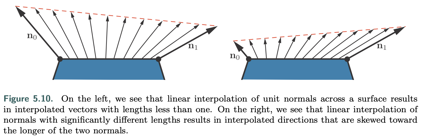
- Implementations often normalize interpolated vectors before and after interpolation, i.e., in both the vertex and pixel shaders. Unlike the surface normals, vectors that point toward specific locations, such as the view vector and the light vector for punctual lights, are typically not interpolated. Instead, the interpolated surface position is used to compute these vectors in the pixel shader.
![picture 0]()
- The vertex shader transforms the surface geometry into “the appropriate coordinate system.” For example, if rendered scenes are expected to include huge numbers of lights, world space might be chosen to avoid transforming the light positions. Alternately, camera space might be preferred, to better optimize pixel shader operations relating to the view vector and to possibly improve precision (Section 16.6).
some applications choose the faceted appearance of per-primitive shading evaluation for stylistic reasons. This style is often referred to as flat shading. In principle, flat shading could be performed in the geometry shader, but recent implementations typically use the vertex shader. This is done by associating each primitive’s properties with its first vertex and disabling vertex value interpolation. Disabling interpolation (which can be done for each vertex value separately) causes the value from the first vertex to be passed to all pixels in the primitive.
Implementation Examples
- In most typical rendering applications, varying values for material properties such as $c_{surface}$ would be stored in vertex data or, more commonly, in textures (Chapter 6).
This implementation will use the shader’s dynamic branching capabilities to loop over all light sources. While this straightforward approach can work well for reasonably simple scenes, it does not scale well to large and geometrically complex scenes with many light sources. Rendering techniques to efficiently handle large light counts will be covered in Chapter 20.
- Shading models are not implemented in isolation, but in the context of a larger rendering framework.
- Before the shader code proper, the shader source includes definitions of the shader inputs and outputs.
Since these are point lights, the definition for each one includes a position and a color. These are defined as vec4 instead of vec3 to conform to the restrictions of the GLSL std140 data layout standard. Although, as in this case, the std140 layout can lead to some wasted space, it simplifies the task of ensuring consistent data layout between CPU and GPU, which is why we use it in this sample. The array of Light structs is defined inside a named uniform block, which is a GLSL feature for binding a group of uniform variables to a buffer object for faster data transfer. The array length is defined to be equal to the maximum number of lights that the application allows in a single draw call. As we will see later, the application replaces the MAXLIGHTS string in the shader source with the correct value (10 in this case) before shader compilation. The uniform integer uLightCount is the actual number of active lights in the draw call.
Our goal here is to give a sense of how shaders are treated as separate processors, with their own programming environment. For actual code interpretation, please refer to original book.
pixel shader code:
1
2
3
4
5
6
7
8
9
10
11
12
13
14
15
16
17
18
19
20
21
22
23
24
25
26
27
28
29
in vec3 vPos;
in vec3 vNormal;
out vec4 outColor;

struct Light {
  vec4 position;
  vec4 color;
};
uniform LightUBlock {
  Light uLights[MAXLIGHTS];
};
uniform uint uLightCount;

vec3 lit(vec3 l, vec3 n, vec3 v) {
  vec3 r_l = reflect(-l, n);
  float s = clamp(100.0 * dot(r_l, v) - 97.0, 0.0, 1.0);
  vec3 highlightColor = vec3(2,2,2);
  return mix(uWarmColor , highlightColor , s);
}
void main () {
  vec3 n = normalize(vNormal);
  vec3 v = normalize(uEyePosition.xyz - vPos);
  outColor = vec4(uFUnlit , 1.0);
  for (uint i = 0u; i < uLightCount; i++) {
    vec3 l = normalize(uLights[i].position.xyz - vPos);
    float NdL = clamp(dot(n, l), 0.0, 1.0);
    outColor.rgb += NdL * uLights[i].color.rgb * lit(l,n,v);
  }
}
vertex shader code:
1
2
3
4
5
6
7
8
9
10
11
12
13
14
15
16
17
18
layout(location=0) in vec4 position;
layout(location=1) in vec4 normal;
out vec3 vPos;
out vec3 vNormal;

void main() {
  vec4 worldPosition = uModel * position;
  vPos = worldPosition.xyz;
  vNormal = (uModel * normal).xyz;
  gl_Position = viewProj * worldPosition;
}

var fSource = document.getElementById("fragment").text.trim();
var maxLights = 10;
fSource = fSource.replace(/MAXLIGHTS/g, maxLights.toString());
var fragmentShader = gl.createShader(gl.FRAGMENT_SHADER);
gl.shaderSource(fragmentShader , fSource);
gl.compileShader(fragmentShader);
Material Systems
Composing Shaders
One of the most important tasks of a material system is dividing various shader functions into separate elements and controlling how these are combined.
- Composing surface shading with geometric processing, such as rigid transforms, vertex blending, morphing, tessellation, instancing, and clipping. These bits of functionality vary independently: Surface shading depends on the material, and geometry processing depends on the mesh.
- Composing surface shading with compositing operations such as pixel discard and blending. This is particularly relevant to mobile GPUs, where blending is typically performed in the pixel shader. It is often desirable to select these operations independently of the material used for surface shading.
- Composing the operations used to compute the shading model parameters with the computation of the shading model itself. This allows authoring the shading model implementation once and reusing it in combination with various different methods for computing the shading model parameters.
- Composing individually selectable material features with each other, the selection logic, and the rest of the shader. This enables writing the implementation of each feature separately.
- Composing the shading model and computation of its parameters with light source evaluation: computing the values of $c_{light}$ and $\vec{l}$ at the shaded point for each light source. Techniques such as deferred rendering change the structure of this composition.
GPU shaders do not allow for post-compilation linking of code fragments. The program for each shader stage is compiled as a unit. The only way that the material system can implement all these types of composition is at the source-code level. This primarily involves string operations such as concatenation and replacement, often performed via C-style preprocessing directives such as #include, #if, and #define.
Today much of the functionality variation, such as the number of lights, is handled at runtime. However, adding a large amount of functional variation to a shader incurs a different cost: an increase in register count and a corresponding reduction in occupancy, and thus performance. So, compile-time variation is still valuable. It avoids including complex logic that will never be executed.
Even though the full burden is no longer handled only at compile time, the overall complexity and number of variations keep increasing, so a large number of shader variants still need to be compiled. Although these are sometimes presented as mutually exclusive system architectures, these strategies can be—and usually are—combined in the same system:
- Code reuse—Implementing functions in shared files, using #include preprocessor directives to access those functions from any shader that needs them.
- Subtractive—Use a combination of compile-time preprocessor conditionals and dynamic branching to remove unused parts and to switch between mutually exclusive alternatives.
- Additive—Various bits of functionality are defined as nodes with input and output connectors, and these are composed together.
- Template-based—An interface is defined, into which different implementations can be plugged as long as they conform to that interface. This is a bit more formal than the additive strategy and is typically used for larger chunks of func- tionality.
A common example for such an interface is the separation between the calculation of shading model parameters and the computation of the shading model itself. The Unreal Engine has different “material domains,” including the Surface domain for computing shading model parameters and the Light Function domain for computing a scalar value that modulates clight for a given light source. A similar “surface shader” structure also exists in Unity .
deferred shading techniques (discussed in Chapter 20) enforce a similar structure, with the G-buffer serving as the interface.
Multi-platform Material Systems
Besides composition, there are several other important design considerations for modern material systems, such as the need to support multiple platforms with minimal duplication of shader code.
This includes variations in functionality to account for performance and capability differences among platforms, shading languages, and APIs.
- The Destiny shader system is a representative solution to this type of problem. It uses a proprietary preprocessor layer that takes shaders written in a custom shading language dialect. This allows writing platform-independent materials with automatic translation to different shading languages and implementations.
Good Performance
Besides specialized compilation of shading variants, there are a few other common optimizations the material system can perform.
- The Destiny shader system and the Unreal Engine automatically detect computations that are constant across a draw call and move it outside of the shader.
- Another example is the scoping system used in Destiny to differentiate between constants that are updated at different frequencies (e.g., once per frame, once per light, once per object) and update each set of constants at the appropriate times to reduce API overhead.
implementing a shading equation is a matter of deciding what parts can be simplified, how frequently to compute various expressions, and how the user is able to modify and control the appearance.