Transparency, Alpha, Compositing
There are many different ways in which semitransparent objects can allow light to pass through them. For rendering algorithms, these can be roughly divided into:
- Light-based effects are those in which the object causes light to be attenuated or diverted, causing other objects in the scene to be lit and rendered differently.
- View-based effects are those in which the semitransparent object itself is being rendered.
In this section we will deal with the simplest form of view-based transparency, in which the semitransparent object acts as an attenuator of the colors of the objects behind it.
More elaborate view- and light-based effects such as frosted glass, the bending of light (refraction), attenuation of light due to the thickness of the transparent object, and reflectivity and transmission changes due to the viewing angle are discussed in later chapters.
Screen-door Transparency
One of the simplest ways to give the illusion of transparency is to use a screen-door transparency. The idea is to render the transparent triangle with a pixel-aligned checkerboard fill pattern. That is, every other pixel of the triangle is rendered, thereby leaving the object behind it partially visible.
- A major drawback of this method is that often only one transparent object can be convincingly rendered on one area of the screen.
- Also, the 50% checkerboard is limiting. Other larger pixel masks could be used to give other percentages, but these tend to create detectable patterns。
- Advantage: simplicity. Transparent objects can be rendered at any time, in any order, and no special hardware is needed.
This same idea is used for antialiasing edges of cutout textures, but at a subpixel level, using a feature called alpha to coverage (Section 6.6).
Stochastic Transparency
Stochastic transparency uses subpixel screen-door masks combined with stochastic sampling.
A reasonable, though noisy, image is created by using random stipple patterns to represent the alpha coverage of the fragment.
- A large number of samples per pixel is needed for the result to look reasonable, as well as a sizable amount of memory for all the subpixel samples.
- What is appealing is that no blending is needed, and antialiasing, transparency, and any other phenomena that creates partially covered pixels are covered by a single mechanism.
Alpha Blending
Most transparency algorithms blend the transparent object’s color with the color of the object behind it. When an object is rendered on the screen, an RGB color and a z-buffer depth are associated with each pixel. Another component, called alpha (α), can also be defined for each pixel the object covers.
Alpha is a value describing the degree of opacity and coverage of an object fragment for a given pixel.
A pixel’s alpha can represent either opacity, coverage, or both, depending on the circumstances.
Blending Order
Over Operator
To make an object appear transparent, it is rendered on top of the existing scene with an alpha of less than 1.0. Each pixel covered by the object will receive a resulting RGBα (also called RGBA) from the pixel shader. Blending this fragment’s value with the original pixel color is usually done using the over operator, as follows:
\[\mathbf{c_O} = \alpha_S\mathbf{c_S} + (1-\alpha_S)\mathbf{c_d}\]where $c_s$ is the color of the transparent object (called the source), $α_s$ is the object’s alpha, $c_d$ is the pixel color before blending (called the destination), and $c_o$ is the resulting color due to placing the transparent object over the existing scene.
Transparency done this way works, in the sense that we perceive something as trans- parent whenever the objects behind can be seen through it. Using over simulates the real-world effect of a gauzy fabric. The view of the objects behind the fabric are partially obscured—the fabric’s threads are opaque. In practice, loose fabric has an alpha coverage that varies with angle.
The over operator is less convincing simulating other transparent effects, most notably viewing through colored glass or plastic. A red filter held in front of a blue object in the real world usually makes the blue object look dark, as this object reflects little light that can pass through the red filter. (physical transmittance is discussed in Sections 14.5.1 and 14.5.2.)
Additive Blending
\(\mathbf{c_O}=\alpha_S\mathbf{c_S}+\mathbf{c_d}\) This blending mode can work well for glowing effects such as lightning or sparks that do not attenuate the pixels behind but instead only brighten them.
For several layered semitransparent surfaces, such as smoke or fire, additive blending has the effect of saturating the colors of the phenomenon
To render transparent objects properly, we need to draw them after the opaque objects. This is done by rendering all opaque objects first with blending off, then rendering the transparent objects with over turned on.
In theory we could always have over on, since an opaque alpha of 1.0 would give the source color and hide the destination color, but doing so is more expensive, for no real gain.
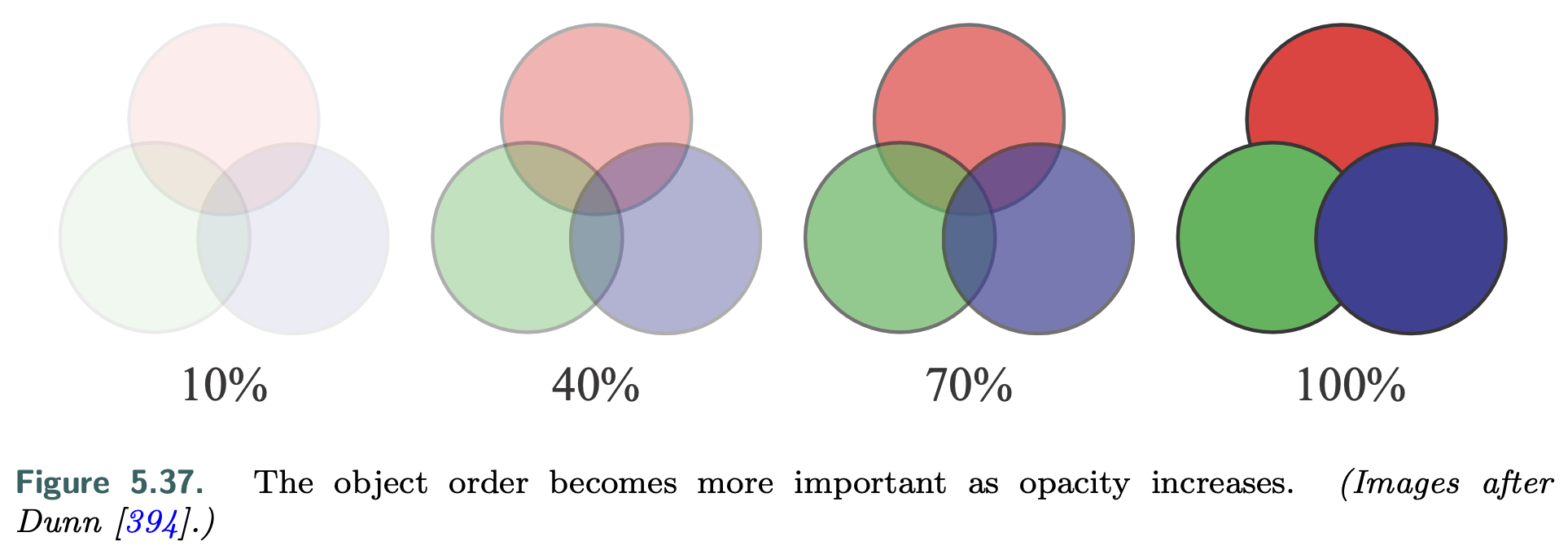
A limitation of the z-buffer is that only one object is stored per pixel. If several transparent objects overlap the same pixel, the z-buffer alone cannot hold and later resolve the effect of all the visible objects. When using over the transparent surfaces at any given pixel generally need to be rendered in back-to-front order. Not doing so can give incorrect perceptual cues.
Sort by Centroid
One way to achieve this ordering is to sort individual objects by, say, the distance of their centroids along the view direction. This rough sorting can work reasonably well, but has a number of problems under various circumstances.
- the order is just an approximation, so objects classified as more distant may be in front of objects considered nearer.
- Objects that interpenetrate are impossible to resolve on a per-mesh basis for all view angles, short of breaking each mesh into separate pieces.
because of its simplicity and speed, as well as needing no additional memory or special GPU support, performing a rough sort for transparency is still commonly used.
If implemented, it is usually best to turn off z-depth replacement when performing transparency. That is, the z-buffer is still tested normally, but surviving surfaces do not change the z-depth stored; the closest opaque surface’s depth is left intact. In this way, all transparent objects will at least appear in some form, versus suddenly appearing or disappearing when a camera rotation changes the sort order.
Other techniques can also help improve the appearance, such as drawing each transparent mesh twice as you go, first rendering backfaces and then frontfaces. (Further Reading)
Under Operator
The over equation can also be modified so that blending front to back gives the same result. This blending mode is called the under operator:
\[\mathbf{c_O=(\alpha_d c_d+(1-\alpha_d)\alpha_S c_S)/a_O}\] \[\mathbf{a_O=\alpha_S(1-\alpha_d)+\alpha_d=\alpha_S-\alpha_S\alpha_d+\alpha_d}\]Note that under requires the destination to maintain an alpha value, which over does not. In other words, the destination—the closer transparent surface being blended under—is not opaque and so needs to have an alpha value. The under formulation is like over, but with source and destination swapped. Also, notice that the formula for computing alpha is order-independent.
Order-Independent Transparency
The under equations are used by drawing all transparent objects to a separate color buffer, then merging this color buffer atop the opaque view of the scene using over.
Another use of the under operator is for performing an order-independent transparency (OIT) algorithm known as depth peeling.
Order-independent means that the application does not need to perform sorting. The idea behind depth peeling is to use two z-buffers and multiple passes.
- a rendering pass is made so that all surfaces’ z-depths, including transparent surfaces, are in the first z-buffer.
- In the second pass all transparent objects are rendered.
- If the z-depth of an object matches the value in the first z-buffer, we know this is the closest transparent object and save its RGBα to a separate color buffer.
- We also “peel” this layer away by saving the z-depth of whichever transparent object, if any, is beyond the first z-depth and is closest. This z-depth is the distance of the second-closest transparent object.
- Successive passes continue to peel and add transparent layers using under operator.
- We stop after some number of passes and then blend the transparent image atop the opaque image.
Several variants on this scheme have been developed. (Further Reading)
One problem with depth peeling is knowing how many passes are sufficient to capture all the transparent layers.
- One hardware solution is to provide a pixel draw counter, which tells how many pixels were written during rendering; when no pixels are rendered by a pass, rendering is done.
- The advantage of using under is that the most important transparent layers—those the eye first sees—are rendered early on.
- Each transparent surface always increases the alpha value of the pixel it covers. If the alpha value for a pixel nears 1.0, the blended contributions have made the pixel almost opaque, and so more distant objects will have a negligible effect. Front-to-back peeling can be cut short when the number of pixels rendered by a pass falls below some minimum, or a fixed number of passes can be specified.
While depth peeling is effective, it can be slow, as each layer peeled is a separate rendering pass of all transparent objects.
- dual depth peeling, where two depth peel layers, the closest and the farthest remaining, are stripped off in each pass, thus cutting the number of rendering passes in half.
- a bucket sort method that captures up to 32 layers in a single pass. One drawback of this type of approach is that it needs considerable memory to keep a sorted order for all layers.
The problem of blending transparent objects together properly at interactive rates is not one in which we are lacking algorithms, it is one of efficiently mapping those algorithms to the GPU.
- In the A-buffer, each triangle rendered creates a coverage mask for each screen grid cell it fully or partially covers. Each pixel stores a list of all relevant fragments. Opaque fragments can cull out fragments behind them, similar to the z-buffer. All the fragments are stored for transparent surfaces. Once all lists are formed, a final result is produced by walking through the fragments and resolving each sample.
- The idea of creating linked lists of fragments on the GPU was made possible through new functionality exposed in DirectX 11. The features used include unordered access views (UAVs) and atomic operations.
- This algorithm works by rasterizing each transparent surface and inserting the fragments generated in a long array. Along with the colors and depths, a separate pointer structure is generated that links each fragment to the previous fragment stored for the pixel.
- A separate pass is then performed, where a screen-filling quadrilateral is rendered so that a pixel shader is evaluated at every pixel.
- This shader retrieves all the transparent fragments at each pixel by following the links. Each fragment retrieved is sorted in turn with the previous fragments. This sorted list is then blended back to front to give the final pixel color.
Because blending is performed by the pixel shader, different blend modes can be specified per pixel, if desired.
- The A-buffer has the advantage that only the fragments needed for each pixel are allocated, as does the linked list implementation on the GPU.
- This in a sense can also be a disadvantage, as the amount of storage required is not known before rendering of a frame begins. A scene with hair, smoke, or other objects with a potential for many overlapping transparent surfaces can produce a huge number of fragments.
Multi-Layer Alpha Blending
GPUs normally have memory resources such as buffers and arrays allocated in advance, and linked-list approaches are no exception. Users need to decide how much memory is enough, and running out of memory causes noticeable artifacts. An approach tackling this problem, multi-layer alpha blending, uses a GPU feature introduced by Intel called pixel synchronization. (Further Reading)
- This capability provides programmable blending with less overhead than atomics. Their approach reformulates storage and blending so that it gracefully degrades if memory runs out.
- A rough sort order can benefit their scheme. DirectX 11.3 introduced rasterizer order views (Section 3.8), a type of buffer that allows this trans- parency method to be implemented on any GPU supporting this feature.
- Mobile devices have a similar technology called tile local storage that permits them to implement multi-layer alpha blending. Such mechanisms have a performance cost, however, so this type of algorithm can be expensive.
Weighted Average
Weighted sum and weighted average transparency techniques are order-independent, are single-pass, and run on almost every GPU. The problem is that they do not take into account the ordering of the objects.While nearly opaque objects give poor results, this class of algorithms is useful for visualization and works well for highly transparent surfaces and particles.
Weighted Sum:
\[\mathbf{c_O}=\sum_{i=1}^n\alpha_ic_i+c_d(1-\sum_{i=1}^n\alpha_i)\]The two sums are accumulated and stored separately as transparent surfaces are rendered, and at the end of the transparency pass, the equation is evaluated at each pixel.
Problems with this method are that the first sum saturates, i.e., generates color values greater than (1.0, 1.0, 1.0), and that the background color can have a negative effect, since the sum of the alphas can surpass 1.0.
The weighted average equation is usually preferred because it avoids these problems:
\[\mathbf{c_{sum}}=\sum_{i=1}^n\alpha_ic_i, \alpha_{sum}=\sum_{i=1}^n\alpha_i\] \[c_{wavg}=\frac{c_{sum}}{\alpha_{sum}},\alpha_{avg}=\frac{\alpha_{sum}}{n}\] \[u=(1-\alpha_{avg})^n\] \[\mathbf{c_O}=(1-u)c_{wavg}+uc_d\]The first line represents the results in the two separate buffers generated during transparency rendering. Each surface contributing to $c_{sum}$ is given an influence weighted by its alpha.
By dividing $c_{sum}$ by $α_{sum}$ we get a weighted average transparency color. The value $α_{avg}$ is the average of all alpha values. The value u is the estimated visibility of the destination (the opaque scene) after this average alpha is applied n times, for n transparent surfaces. The final line is effectively the over operator, with (1 − u) representing the source’s alpha.
One limitation with weighted average is that, for identical alphas, it blends all col- ors equally, regardless of order. Weighted blended order-independent transparency (WB-OIT) gives a more convincing result. In this formulation, the distance to the surface also affects the weight, with closer surfaces given more influence. Also, rather than averaging the alphas, $u$ is computed by multiplying the terms $(1 − α_i)$ together and subtracting from one, giving the true alpha coverage of the set of surfaces.
A drawback is that objects close to one another in a large environment can have nearly equal weightings from distance, making the result little different than the weighted average. Also, as the camera’s distance to the transparent objects changes, the depth weightings may then vary in effect, but this change is gradual.
This method could be extended to include a plausible transmission color effect.
As noted earlier, all the transparency algorithms discussed in this section blend various colors instead of filtering them, mimicking pixel coverage.
To give a color filter effect, the opaque scene is read by the pixel shader and each transparent surface multiplies the pixels it covers in this scene by its color, saving the result to a third buffer. This buffer, in which the opaque objects are now tinted by the transparent ones, is then used in place of the opaque scene when resolving the transparency buffers. This method works because, unlike transparency due to coverage, colored transmission is order-independent.
Given the wide variety of types of transparent content, rendering methods, and GPU capabilities, there is no perfect solution for rendering transparent objects.