BRDF Models for Surface Reflection
With few exceptions, the specular BRDF terms used in physically based rendering are derived from microfacet theory. In the case of specular surface reflection, each microfacet is a perfectly smooth Fresnel mirror. Recall that such mirrors reflect each incoming ray of light in a single reflected direction. This means that the micro-BRDF $f_\mu(l, v, m)$ for each facet is equal to zero unless $v$ is parallel to the reflection of $l$. For given $l$ and $v$ vectors, this configuration is equivalent to the case where the microfacet normal $m$ is aligned with a vector pointing exactly halfway between $l$ and $v$. This vector is the half vector $h$. It is computed by adding $v$ and $l$ and normalizing the result.
\[h=\frac{l+v}{\|l+v\|}\tag{9.33}\]When deriving a specular microfacet model from Equation 9.26, the fact that the Fresnel mirror micro-BRDF $f_\mu(l, v, m)$ is equal to zero for all $m \neq h$ is convenient, since it collapses the integral into an evaluation of the integrated function at $m = h$. Doing so yields the specular BRDF term
\[f_{spec}(l, v) = \frac{F(h,l) G_2(l, v,h)D(h)}{4\mid n\cdot l\mid\mid n\cdot v\mid}.\tag{9.34}\]Details on the derivation can be found in publications by Walter et al., Heitz, and Hammon. Hammon also shows a method to optimize the BRDF implementation by calculating $n \cdot h$ and $l \cdot h$ without calculating the vector $h$ itself.
We use the notation $f_{spec}$ for the BRDF term in Equation 9.34 to denote that it models only surface (specular) reflection. In a full BRDF, it will likely be paired with an additional term that models subsurface (diffuse) shading. To provide some intuition on Equation 9.34, consider that only those microfacets that happen to have their normals aligned with the half vector $(m = h)$ are correctly oriented to reflect light from $l$ into $v$. Thus, the amount of reflected light depends on the concentration of microfacets with normals equal to $h$. This value is given by $D(h)$, the fraction of those microfacets that are visible from both the light and view directions, which is equal to $G_2(l, v, h)$, and the portion of light reflected by each of those microfacets, which is specified by $F(h, l)$. In the evaluation of the Fresnel function, the vector $h$ substitutes for the surface normal, e.g., when evaluating the Schlick approximation in Equation 9.16.
The use of the half vector in the masking-shadowing function allows for a minor simplification. Since the angles involved can never be greater than $90^\circ$, the $\chi^+$ terms in Equations 9.24, 9.31, and 9.32 can be removed.
Normal Distribution Functions
The normal distribution function has a significant effect on the appearance of the rendered surface. The shape of the NDF, as plotted on the sphere of microfacet normals, determines the width and shape of the cone of reflected rays (the specular lobe), which in turn determines the size and shape of specular highlights. The NDF affects the overall perception of surface roughness, as well as more subtle visual aspects such as whether highlights have a distinct edge or are surrounded by haze.
However, the specular lobe is not a simple copy of the NDF shape. It, and thus the highlight shape, is distorted to a greater or lesser degree depending on surface curvature and view angle. This distortion is especially strong for flat surfaces viewed at glancing angles.
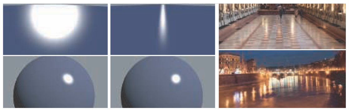
Figure 9.35. The images on the left are rendered with the non-physical Phong reflection model. This model’s specular lobe is rotationally symmetrical around the reflection vector. Such BRDFs were often used in the early days of computer graphics. The images in the center are rendered with a physically based microfacet BRDF. The top left and center show a planar surface lit at a glancing angle. The top left shows an incorrect round highlight, while the center displays the characteristic highlight elongation on the microfacet BRDF. This center view matches reality, as shown in the photographs on the right. The difference in highlight shape is far more subtle on the sphere shown in the lower two rendered images, since in this case the surface curvature is the dominating factor for the highlight shape.